T3 Install & Operation Manual
Safety
This appliance can be used by children aged from 8 years and above and persons with reduced physical, sensory or mental capabilities or lack of experience and knowledge if they have been given supervision or instruction concerning use of the appliance in a safe way and understand the hazards involved. Children shall not play with the appliance. Cleaning and user maintenance shall not be made by children without supervision.
The appliance shall only be maintained and repaired by authorized technicians who are properly trained and certified. The appliance should be isolated from the electricity supply before removal of any covers. Great care must be employed when working with high pressure carbon dioxide, and in no cases should the maximum operating pressure of 0.4MPa (4 bar) be exceeded.
- The appliance is not suitable for installation in an area where a water jet could be used.
- The appliance shall not be intended for use in lobbies or locations of egress, such as a hallway or public corridor.
- The appliance has to be placed in a horizontal position.
WARNING: Keep ventilation openings in the appliance enclosure or in the built-in structure clear of obstruction.
WARNING: When positioning the appliance, ensure the supply cord is not trapped or damaged.
WARNING: Do not locate multiple portable socket-outlets or portable power supplies at the rear of the appliance.
WARNING: Increased risk of a leak could occur through improper handling, movement or use.
This appliance is intended to be used in household and similar applications such as:-
- Staff kitchen areas in shops, offices and other working environments
- Farm houses and by clients in hotels, motels and other residential type environments
- Bed and breakfast type environments
- Catering and similar non-retail applications
A-weighted emission sound pressure level is below 70 dB(A)
 | R290 is a refrigerant-grade propane used on a wide range of commercial refrigeration and air conditioning units. A highly pure propane, it has a low environmental impact and nominal global warming potential (GWP), meaning it possesses no qualities that can destroy the ozone layer. R290 also is the preferred hydrocarbon alternative of the Environmental Protection Agency (EPA), substituting more harmful fluorocarbon refrigerants like R22, R134a, R404a and R502. Units with R290 can only be maintained and repaired by authorized technicians who are properly trained and certified. |
|---|
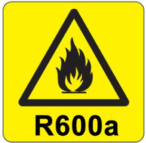 | R600a is a refrigerant-grade isobutane used on a wide range of commercial refrigeration and air conditioning units. A highly pure isobutane, it has a low environmental impact and nominal global warming potential (GWP), meaning it possesses no qualities that can destroy the ozone layer. R600a also is the preferred hydrocarbon alternative of the Environmental Protection Agency (EPA), substituting more harmful fluorocarbon refrigerants like R22, R134a, R404a and R502. Units with R600a can only be maintained and repaired by authorized technicians who are properly trained and certified. |
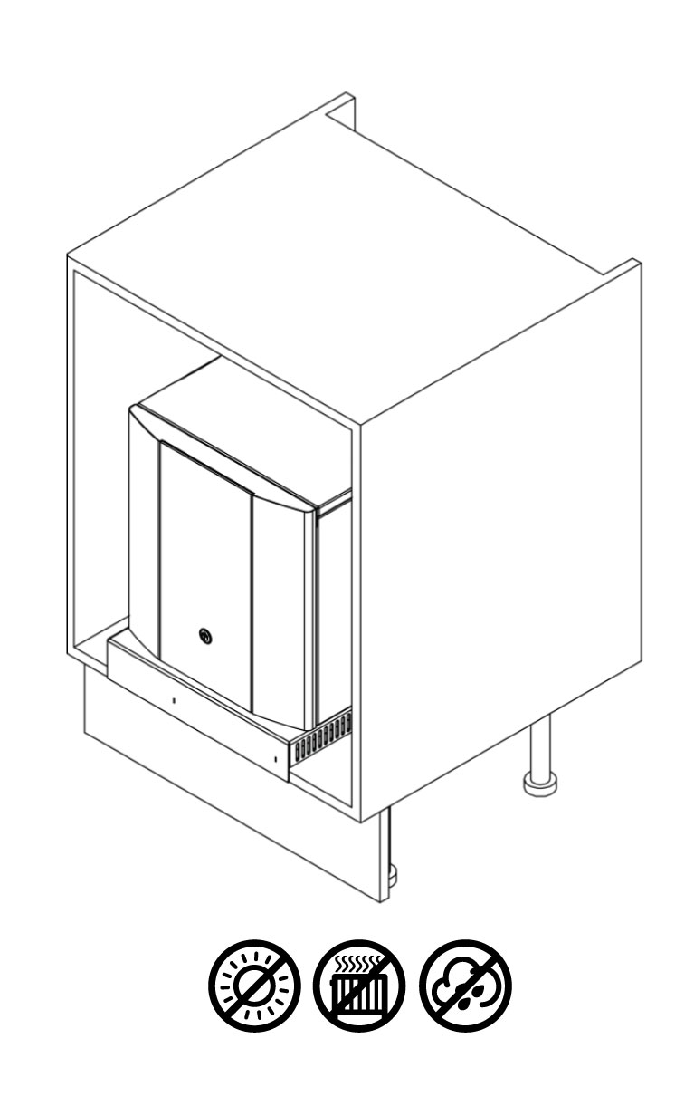
- Always place the dispenser in its vertical position, on a surface which can capably support its weight.
- During use the unit must remain in its upright position.
- Adequate ventilation must be allowed for. Always install this unit with the Simple-fit Vent Kit to ensure adequate air flow. Installing the unit without the Simple-fit Vent Kit will invalidate the warranty.
- Keep the machine away from sunlight, heat and moisture.
- Power and water supply points must be available near the dispenser, and must meet the criteria specified in the ‘Specification’ section of this manual.
- The environment where the unit is installed must be free of dust and corrosive/explosive gases.
Waste Electrical Products:
|  |
Specification
Specification 230v
| COOLING SYSTEM | Stainless steel direct chill coil encased in a solid-block system for instant response cool down action. Ultra efficiency compression system with capillary control. Environmentally friendly R290 refrigerant. |
| DISPENSE | Quadra Neck Faucet with ergonomically designed and situated light touch sensitive controls. |
| POWER SUPPLY | 230-240V~ AC (50Hz) |
| FUSE RATING | 10A |
| COLD TEMPERATURE FROM | 2°C |
| CHILLED & SPARKLING CAPACITY | 50L (ProCore) 80L (ProCore+) |
| HOT TEMPERATURE UP TO | 96°C |
| HOT TANK VOLUME | 1.7L |
| HOT TANK CAPACITY | 15L/h |
| MAXIMUM RUNNING POWER CONSUMPTION - CHILLED, AMBIENT & HOT | 1.6kW-230V |
| MAXIMUM RUNNING POWER CONSUMPTION - CHILLED, AMBIENT, SPARKLING & HOT | 1.7kW-230V |
| RATED CURRENT - CHILLED, AMBIENT & HOT | 7.0A ProCore 7.1A ProCore+ |
| RATED CURRENT - CHILLED, AMBIENT, SPARKLING & HOT | 7.3A ProCore 7.5A ProCore+ |
| QUANTITY OF REFRIGERATION GAS | R290 33g ProCore R290 40g ProCore+ |
| DIMENSIONS | (w x d x h) 320 x 471 x 375mm |
| WEIGHT | 27Kg MAX |
| WATER CONNECTION- COLD | 3/4" BSP |
| WATER CONNECTION- HOT | 3/4” BSP |
| INLET WATER TEMPERATURE | Up to 25°C |
| MINIMUM TO MAXIMUM INLET WATER PRESSURE | 0.05MPa (0.5 bar) - 1.0 MPa (10 bar) Internally regulated to 0.2 MPa (2 bar) - Cold Internally regulated to 0.3 MPa (3 bar) - Hot |
| CO2 CONNECTION | 1/4” Push Fit |
| CO2 PRESSURE | 0.4MPa (4 Bar) Maximum |
| MINIMUM TO MAXIMUM AMBIENT ROOM OPERATING TEMPERATURE | 5°C-32°C |
| CLIMATIC CLASS | N |
Specification 115v
| COOLING SYSTEM | Stainless steel direct chill coil encased in a solid-block system for instant response cool down action. Ultra efficiency compression system with capillary control. Environmentally friendly R290/R600a refrigerant. |
| DISPENSE | Quadra Neck Faucet with ergonomically designed and situated light touch sensitive controls. |
| POWER SUPPLY | 110-120V~ AC (60Hz) |
| FUSE RATING | 10A |
| COLD TEMPERATURE FROM | 35°F |
| CHILLED & SPARKLING CAPACITY | 13.2 Gal/h (Procore) 21 Gal/h (Procore +) |
| HOT TEMPERATURE UP TO | 187°F |
| HOT TANK VOLUME | 0.4 Gal |
| HOT TANK CAPACITY | 4 Gal/h |
| MAXIMUM RUNNING POWER CONSUMPTION - CHILLED, AMBIENT & HOT | 1kW-115V ProCore 1kW-115V ProCore+ |
| MAXIMUM RUNNING POWER CONSUMPTION - CHILLED, AMBIENT, SPARKLING & HOT | 1.1kW-115V ProCore 1.1kW-115V ProCore+ |
| RATED CURRENT - CHILLED, AMBIENT & HOT | 9.2A ProCore 9.2A ProCore+ |
| RATED CURRENT - CHILLED, AMBIENT, SPARKLING & HOT | 9.6A ProCore 9.6A ProCore+ |
| QUANTITY OF REFRIGERATION GAS | ProCore R600a 20g ProCore+ R290 37g |
| DIMENSIONS | (w x d x h) 12.6 x 18.5 x 14.8'' |
| WEIGHT | 60lbs MAX |
| WATER CONNECTION- COLD | 3/4” BSP |
| WATER CONNECTION- HOT | 3/4" BSP |
| INLET WATER TEMPERATURE | Up to 77°F |
| MINIMUM TO MAXIMUM INLET WATER PRESSURE | 7.3psi (0.05MPa) - 145psi (1.0MPa) Internally regulated to 29psi (0.2MPa) |
| CO2 CONNECTION | 1/4” Push Fit |
| CO2 PRESSURE | 58psi (0.4Mpa) Maximum |
| MINIMUM TO MAXIMUM AMBIENT ROOM OPERATING TEMPERATURE | 41°F - 90°F |
| CLIMATIC CLASS | N |
Model Overview
Introduction
The T3 & T3+ epitomises cutting-edge design and innovation with its contoured tap and compact ProCore unit. This is our most discreet range and will fit into any environment seamlessly.
The ProCore dispenser is a cooler designed to provide chilled and carbonated water. All the materials and components are tested during the entire production process in order to satisfy all expectations.

Component/Feature Overview
T3 Tap - Major Components
Contents:
1 no T3
1 no Top Plate with Control Panel
1 no Drip Tray
1 no 1.0m x 6mm Insulated Water Pipe
1 no Connector Cable
1 no Waste Drain Pipe
1 no Fixings Set

ProCore Electronic - Major Components
Contents:
1 no Undercounter Unit
1 no Power Cord Set
1 no Co2 Regulator with Gauge & Connection tube*
1 no ProCore Simple-fit Ventilation Kit

Please Note:
Mains Installation Kit & Filters are supplied as extra items
according to individual ordering requirement.
*Sparkling versions only
Dimensions
NOTE: Monofit tap base 11.5mm taller.


Installation
Installation Requirements
Identify a suitable location for the ProCore unit. It should be positioned within 1.0m of the faucet, and within 2.0m of suitable services connections. Ensure to allow enough space for the Simple-fit Vent Kit which must be installed with the unit.
The ProCore unit must be installed in accordance with the relevant requirements of:
- The appropriate building regulations by application of either The Building Regulations (England and Wales), The Building Regulations (Scotland) or The Building Regulations (Northern Ireland). In territories other than those listed the local regulations in force must be complied with.
- The Water Supply (Water Fittings) Regulations (England, Wales and Northern Ireland) or The Water Byelaws in Scotland.
The unit must not be installed where it is liable to freeze. If the unit is thought to be frozen it must not be switched on. It should be allowed to thaw and must then be thoroughly inspected to ensure it is undamaged. No water leakage allowed to contact the mains switch or mains inlet coupler.
Service Requirements
- Water: Mains potable water
- CO2: Food Grade CO2 to be supplied
- Electricity: 10A supply – Earth Leakage Protected Required (For USA & Canada, the supply must be protected by a ground-fault circuit interrupter (GFCI))


Ensure worktop is level to allow system to drain.


Cutting Templates
ProCore Vent Base Cutting Template
We recommend you check the dimensions of the ProCore Simple-fit Ventilation Kit using the cutting template prior to cutting the base cabinet.
Download or order the ProCore Vent Base Cutting Template here
Tap & Driptray Cutting Template
We recommend you check the dimensions of the tap and driptray using the cutting template prior to cutting the work surface.
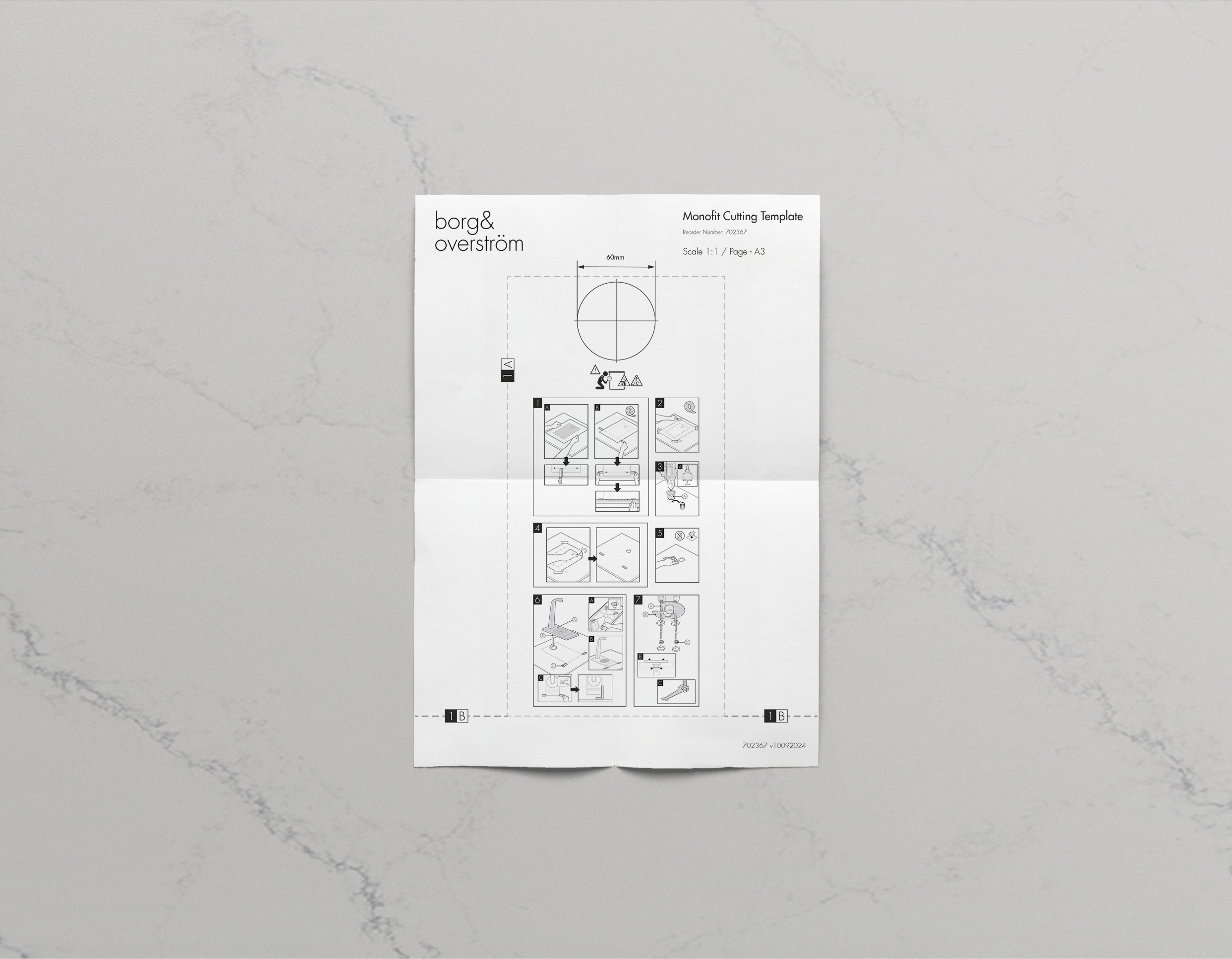
Tap & Driptray Cutting Template - Monofit
We recommend you check the dimensions of the tap and driptray using the cutting template prior to cutting the work surface.
Operation
Tap Control Panel

6. ‘eco’ Mode Symbol 7. Warning Symbol.
Note: Chilled, Sparkling, Ambient & Hot Version shown.
Note: 6 and 7 will only appear when unit is in 'eco' mode or appliance has a fault.
Basic Functions
Dispensing cold water:
Press and hold dispense icon and release to finish dispense
• Chilled icon pulsing – Dry Block is above 10 degrees and chilling down
Dispensing hot water:
Press the unlock icon and then press and hold the hot button to dispense.
• Hot icon pulsing– Hot tank is below 80°C degrees on 230v appliances/ 161°F on 110v appliances.
‘Eco’ Mode:
‘Eco’ mode symbol illuminates when unit is in ‘eco’ mode, to awaken unit press and hold any dispense icon. The appliance will activate ‘eco’ mode in the below instances:
• Dispense inactivity
• Low light level
Warning Symbol:
‘Warning triangle’ symbol will illuminate and flash upon a fault. The number of flashes relates to a particular fault. Click to view fault codes
Connectivity:
• Bluetooth hands free app dispense
• Bluetooth alarmed waste kit enabled
• Foot switch operation enabled
Advanced Functions
Hold ‘Hot Unlock Icon’ for 20 seconds to take the appliance out of commission mode.
To revert to back to commission mode, tap the chilled icon 12 times and hold on the 12th. 2 beeps will indicate the memory reset is complete and will self restart after 2 seconds.
To turn on/off eco mode, tap the chilled icon 7 times and hold on the 7th. 2 beeps will indicate Eco is on and 1 beep will mean Eco is off.
To turn on/off Bluetooth waste, tap the chilled icon 5 times and hold on the 5th. 2 beeps will indicate on and 1 beep will indicate off.
Note: Functions can only be changed within 10 minutes of the appliance being switched on.
Ventilation System Installation
When Borg & Overström undercounter units are installed inside a cabinet or housing, adequate ventilation is essential to ensure that they operate satisfactorily. During a cooling cycle it is normal for the unit to produce heat, and the purpose of ventilation is to provide a supply of air that can absorb the generated heat which would otherwise accumulate inside the cabinet or housing, and reduce the cooling performance of the unit. The amount
of heat generated by the cooling cycle depends directly upon the amount of usage – the higher the usage, the more heat produced. To provide adequate ventilation, this unit must be installed with a Simple-fit Vent Kit to facilitate air flow. Normally this should be enough for all situations. Installing the unit without the Simple-fit Vent Kit will invalidate the warranty.
Important: Before making any cuts into the cupboard or kick board, ensure the area to be cut is free from water pipes or electrical cables. There is a risk of serious injury or death if electrical cables are cut, and significant damage to property if a water pipe is cut.


NOTE: Any obstructions will adversely affect the airflow to the appliance causing potential for poor performance, over heating or fridge failure.
ProCore Installation & Water Connection
The use of a Borg & Overström installation kit is highly recommended. All kits have been designed to include all the parts you need to safely and correctly install our dispensers. To ensure you select the correct kit for the model you’re installing, please visit the website or contact our support team.
All installations of water dispensers must include a water block. A water block is conveniently included in every one of our installation kits. If you’re not a using Borg & Overström installation kit, ensure you install a water block – failure to do so will negate any insurance claims for water damage resulting from water dispenser malfunction.
The Water Block should be installed between the water tap and the appliance’s supply pipe. Using the supplied wrench, rotate indicator ‘P’ anti-clockwise until it reaches Setting 2. Note: If the valve triggers and shuts off the water, it must be manually reset by disconnecting it from the tap.
For installation kits and water blocks please see our store here.
NOTE: The water filters on the supply line to the unit needs to be pre-flushed prior to the water connection to the appliance.


NOTE: To improve sparkling anti-drip & hot draw back cut pipes to shortest length possible.


Hot Tank Commissioning
On initial start up the ‘Unlock’ and ‘Hot’ icon will be flashing, this means the unit is in commissioning mode. To commission the hot tank safely please follow the below steps:
1. Press the ‘Unlock’ icon then hold the ‘Hot’ icon to start filling the hot tank. This will time out after 30s.
2. To continue filling the tank, repeat step 1 as many times as is required until water flows from the tap outlet.
3. After water has been dispensed from the outlet, press and hold the ‘Unlock’ icon for 20 seconds until the unit beeps.
4. The ‘Unlock’ icon will now be solid and the ‘Hot’ icon slowly flashing. The ProCore or ProCore+ is now active.
*Expect dripping on hot dispense until the tank has reached temperature and initial dispense made. This will only occur on first heating cycle on initial start-up.
CO2 Bottle Installation - Sparkling Versions Only


Sparkling Water Flow Rate - Sparkling Versions Only
NOTE: Sparkling water flow rate factory setting = 1.8L (0.4 Gal) per minute MAX. This may need adjusting
depending on inlet pressure. To do so follow below steps:


Once the correct flow rate is achieved place the cover back on to the unit by sliding it in place and replacing the screws.
Maintenance & Cleaning
Sanitisation Guide
The product is supplied from the factory in clean condition, but we recommend that a sanitisation procedure is caried out at the point of installation, according to the sanitisation instruction relevant to this model, which can be found in the respective Instruction & Operation Manual.
NOTE: Failure to use sanitising materials and processes approved and/or recommended by Borg & Overström could invalidate your warranty.

This operation must only be carried out by trained staff.

A sanitisation procedure is recommended every 6 months.

Turn off incoming mains water

Briefly press chilled dispense button to release internal water pressure from the machine.

Remove the existing filter

Use hand gel and put on protective gloves.

Add 25 ml of Hydrogen Peroxide (H2O2 3%) sanitising solution to a clean and empty service filter cartridge.

Connect to filter head.

Turn on incoming water, allow the service filter cartridge to fill

Dispense water using the chilled button. Repeat with sparkling & ambient water buttons.

Leave the solution inside machine for sanitisation to take effect (minimum 5 minutes) while thoroughly cleaning the dispenser externally. (All maintenance operations must be carried out with the dispenser switched off.)

Pay particular attention to the dispense faucet and the push button controls. For this use Sterizen External Sanitiser and Sanitising Wipes.

Remember to include the drip tray. If a Waste Overflow System is fitted, empty this and flush through with a small amount of sanitisation fluid if needed.

Attend to any cosmetic marks as needed. For this we recommend the use of Hydrogen Peroxide (H2O2 3%) sanitising solutions.

Reconnect the power and switch on the dispenser.

When the external cleaning is complete, flush the system through each dispense option (Chilled, Sparkling, Ambient), until clean water appears.

Turn off water and briefly press chilled dispense button to release internal water pressure from the machine.

Remove the service filter. Retain service filter for reuse.

Fit new filter and turn on incoming water supply.

Pre-flush the new filter to waste using the chilled button until 5L of water has flushed through. Repeat this through all dispense options.
  | Please note that this sanitisation fluid contains an active caustic/alkaline agent. Always use responsibly and with care remembering that due to its alkaline nature unnecessary concentrated/prolonged contact with any materials, including metals, can cause damage. Always rinse all contact surfaces after use with clean water. |   | Avoid skin contact and wear protective gloves when handling sanitisation fluids. In the event of any skin contact, flush immediately with clean, cold water. |
Emptying the CO2 Tank


Draining the Hot Tank
NOTE: FIRST ENSURE THE UNIT IS PUT BACK INTO COMMISSION MODE BEFORE PROCEEDING (See Advanced Functions)
To drain the hot tank proceed with the following steps:


Once the tank is fully drained ensure the bung is then fully pushed back in.
Care and Maintenance of Stainless Steel
Introduction
All grades of stainless steel will stain and discolour due to surface deposits and can never be accepted as completely maintenance free. In order to achieve maximum corrosion resistance the surface of the stainless steel must be kept clean. Provided the grade of stainless steel and the surface finish are correctly selected, and cleaning schedules carried out on a regular basis, good performance and long service life are assured.
Factors Affecting Maintenance
Surface contamination and the formation of deposits must be prevented. These deposits may be minute particles of iron or rust from other sources used on the building of new premises and not removed until after the stainless steel items have been fixed. Industrial and even naturally occurring atmospheric conditions can produce deposits which can be equally corrosive, e.g. salt deposits from marine conditions.
The working environment also offers more aggressive conditions e.g. hot humidity, such as in a swimming pool, increases the speed of discolouration and therefore requires the maintenance to be on a more frequent basis. Modern processes use many cleaners, sterilizers and bleaches for hygienic purposes. All these proprietary solutions, when used in accordance with makers instructions are safe but if used incorrectly (e.g. warm or concentrated) can cause discolouration and corrosion on the surface of any quality of stainless steel. Strong acid solutions are sometimes used to clean masonry and tiling of buildings, but they should never be permitted
to come into contact with metals, including stainless steel. If this should happen the acid solution must be removed immediately and copious applications of water.
Maintenance Programme
With care taken during fabrication and installation, cleaning before handling over to the Client should present no special problems, although more attention than normal may be required if the installation period has been prolonged. Where surface contamination is suspected, immediate attention to cleaning after site fixing will encourage a trouble-free product. Food handling, pharmaceutical, aerospace and certain nuclear applications require extremely high levels of cleanliness applicable to each industry.
Advice is often sought concerning the frequency of cleaning stainless steel and the answer is quite simple “clean the metal when it is dirty in order to restore its original appearance”. This may vary from once to four times a year for external applications or it may be once a day for an item in hygienic or aggressive situations. Frequency and cost of cleaning is lower with stainless steel than with many other materials and will often outweigh the initial higher cost of this superior product.
| PROBLEM | CLEANING AGENT | COMMENTS |
|---|---|---|
| Routine cleaning | Soap or mild detergent and water (Such as Fairy Liquid). | Sponge, rinse with clean water, wipe dry if necessary. |
| Fingerprints | Soap or warm water or organic solvent (e.g. Usher/ Walker Thinners No PF8017, acetone, alcohol). | Rinse with clean water, wipe dry if necessary. |
| Stubborn stains and discolouration | Mild cleaning solutions i.e Jiff, Goddard Stainless Steel Care. | Rinse well with clean water, wipe dry if necessary. |
| Rust and other corrosion products. | Oxalic Acid. The cleaning solution should be applied with a swab and allowed to stand for 15-20 minutes before being washed away with water. May continue using Jiff to give final clean. | Rinse well with clean water. (precautions for acid cleaners should be observed). |
| Scratches on surface | Slight scratches. Impregnated nylon pads. Polishing with scuffs dressed with iron free abrasives. For deeper scratches; apply in direction of polishing. Then clean with soap or detergent as per routine cleaning. | Do not use ordinary steel wool - iron particles can become embedded in stainless steel and cause further surface problems. |
Precautions
Acids should only be used for on-site cleaning when all other methods have been proved unsatisfactory. Rubber gloves should be used and care taken to see that acid cleaners are not spilt over adjacent areas. Special precautions are necessary with oxalic acid. Solvents should not be used in closed places. Smoking must be avoided when using solvents.
Advanced Troubleshooting
Fault Diagnostics
| Problem/Report | Possible Cause | Suggested Action |
|---|---|---|
| No Water Dispensing | Power supply turned off | Check the power supply has been fitted properly and turned on. |
| Water Pressure Regulator | Check water flow through the regulator. Replace if necessary. |
|
| Check Tap HMI Control | Check fault codes. | |
| Water isolated from machine | Check water inlet supply. | |
| Commissioning mode | Ensure hot tank is full by dispensing hot option and then take unit out of commissioning mode. | |
| Lock icon not pressed | To dispense from hot, press the lock symbol first then hot shortly after. | |
| No Sparkling Water | No CO2 pressure | Check CO2 bottle, regulator and non-return valve. Supply pressure should be 58 psi (4bar), replace as necessary. |
| Carbonator tank not filling | Check carbonator probe for possible short circuit to ground. Check for pump timeout, cycle power off & on then purge carbonator. |
|
| Poor Quality Carbonation | Incorrect CO2 pressure | Check CO2 bottle, regulator and non-return valve. Supply pressure should be 58 psi (4bar), replace as necessary. |
| Air in carbonator tank | Refer to installation and water connection section to see how to purge the carbonator tank. | |
| Residue in carbonator tank | After prolonged use, a surface film can develop within the carbonator tank. Refer to cleaning and sanitising instructions. | |
| Warm Drinks | Insufficient cooling air flow through the fridge | Check that the condenser is not blocked. Check supply to cooling fans (230V AC). If supply present replace fans. If supply not present move on to the compressor. |
| Compressor not running | Check supply to compressor (230V AC). Check NTC probe is not faulty. Check for system over heat. Allow the unit to cool and check for airflow obstructions. Once the unit has cooled the fridge system will restart. If the problem persists contact technical support. |
|
| Fridge failure | If compressor & fan are running and there is no cooling contact technical support. | |
| Water lying in bottom of machine | Leak in pipe work and/or filter | Contact your distributor. |
| Not all symbols displayed | Unit is in heater commissioning mode | See hot tank commissioning section. |
| Temperature not hot enough | Mid heating cycle | If the hot icon is pulsing then unit is not at correct temperature. Wait for solid light. |
| Temperature probe not installed correctly or damaged | Ensure temperature probe is correctly installed or request replacement. | |
| Water demand too high | See product specification. | |
| Element not working | Check and replace as required. | |
| Dripping | Heater over heating | Ensure temperature probe is correctly fitted and not damaged. |
| Lower temperature using app. | ||
| Continuous or incorrect dispense | Poorly seated HMI lens | Replace lens assembly. |
| Excess water on lens | Ensure you keep lens clean and clear of liquids. | |
| Poor laminar flow | Outlet scaled up | Replace outlet assembly. |
Fault Codes
Internal overheat triggered

Carbonator can not filling

Boiler not heating correctly

Waste kit full

Boiler dry fire



Spares
ProCore/ProCore+ Exploded Parts Diagram
T3/T3+ Exploded Parts Diagram
Spares List
Category 1. Safety Critical Spares
| Part No. | Description | CAH | CSAH | |
|---|---|---|---|---|
| 700922 | CNKB FS-7 Flow Switch | • | • | View in store |
| 720337 | PCBA Main Control Board Assembly | • | • | View in store |
| 702770 | Diaphragm Booster Pump - Low Flow Rate Sparkling Water Pump 230v | • | • | View in store |
| 702800 | Diaphragm Booster Pump - Low Flow Rate Sparkling Water Pump 115v | • | • | View in store |
| 702558 | Cooling Fan 24v with Loom | • | • | View in store |
| 702124 | 1.5KW Hot Tank with Expansion Tank 230v | • | • | View in store |
| 702900 | 800W Hot Tank with Expansion Tank 115v | • | • | View in store |
| 720401 | UV Assembly Spares Kit | • | • | View in store |
| 702078 | FS-16 Flow Switch | • | • | View in store |
| 701094 | Solenoid 3/4” BSP 8mm PF | • | • | View in store |
| 701886 | 8mm Pressure Reducing Valve 2 Bar | • | • | View in store |
| 701076 | 8mm Pressure Reducing Valve 3 Bar | • | • | View in store |
| 701937 | 2:1 Dispense Solenoid Valve 8mm | • | View in store | |
| 701992 | 3:1 Dispense Solenoid Valve 8mm | • | View in store | |
| 637329 | Sparkling Water Flow Control Valve | • | View in store | |
| 462667 | Single Check Valve 5/16" (8mm) PF | • | View in store | |
| 462668 | Single Check Valve 1/4" Push Fit | • | View in store | |
| 702878 | All-in-one Sensor Loom with KK Connectors | • | • | View in store |
| 702787 | Congress Solenoid Loom | • | • | View in store |
| 720365 | Chilled, Ambient & Hot Touch Control Panel (HMI) | • | View in store | |
| 720372 | Chilled, Sparkling, Ambient & Hot Touch Control Panel Assembly (HMI) | • | View in store |
Category 2. Cosmetic Spares
| Part No. | Description | CAH | CSAH | |
|---|---|---|---|---|
| 701938 | Top Panel Undercounter | • | • | View in store |
| 720258 | ProCore Right-Hand Side Panel | • | • | View in store |
| 720255 | ProCore Left-Hand Side Panel | • | • | View in store |
| 720045 | ProCore Door Assembly Complete | • | • | View in store |
| 720587 | T3 Tap Outlet Polished Silver - Retrofit Kit | • | • | View in store |
| 720588 | T3 Tap Outlet Polished Black - Retrofit Kit | • | • | View in store |
| 720411 | T-series & E7 Drip Tray Grill - Polished Steel | • | • | View in store |
| 720450 | T-Series & E7 Drip Tray Grill - Black Plated | • | • | View in store |